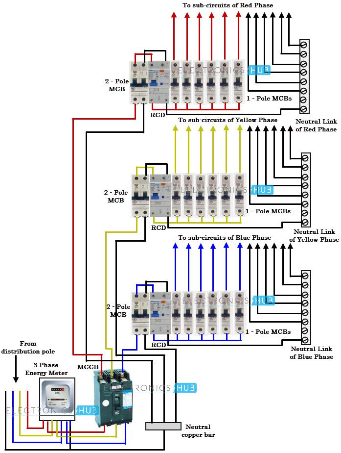
To Be Wired In Accordance With N.E.C. Use Copper Wire (75ºc Min) Only Between Disconnect Switch And Unit. 120/240 volts, 3 wire single phase, 240 volts 3 phase 3 wire, 120/240 3.3 PLUG 2 RELAY1HEAT STRIP-1 1 SCHEMATIC DIAGRAM NOTES: 1. Single Phase Export Transformer, Input Voltage - Transformer 190V AC, 208V AC, 220 V AC, 240V AC, 380V AC, 416V AC, 440V AC, 480V AC, Output Voltage - Transformer 110V AC, 220V AC, VA Rating - Transformer 1 kVA, Mounting - Transformer Wall, Outdoor Rated - Transformer Yes, Voltage Function - Transformer Step Down, Winding Material - Transformer Copper, Hz - Electrical 50 Hz, 60 Hz, Temp.Single Phase Electrical Wiring Installation In A Multi-Story Building - 3 Phase To Single Phase Wiring DiagramMeter Sockets - a meter socket is the base portion of a socket type meter.

Diagram only reveals where to put component in a place relative to other elements inside the circuit. The arrangement is also not plausible, unlike wiring schematics. Lines in the diagram show exactly how every element connects to a another.The rankings of circuit's elements are relative, not accurate. Another thing you will get a circuit diagram would be traces. A circuit is usually composed by several components.
However, it doesn't mean connection between the wires. At times, the wires will cross. It all depends on circuit that is being built.According to earlier, the traces in a 3 Phase To Single Phase Wiring Diagram signifies wires. There are also other components like floor, switch, engine, and inductor. The most common elements are capacitor, resistor, and battery. Every symbol that is shown on the diagram reveals specific circuit element.
3 Phase To Single Phase Wiring Diagram VideoParallel connection is more complicated than the series one. Due to that the electric current in each and every component is similar while voltage of this circuit is total of voltage in each component. It's the easier type of connection as circuit's elements are put within a singular line. The first one is known as series connection. Colors can also be used to differentiate cables.Ordinarily, there are two chief types of circuit connections. There'll be main lines that are represented by L1, L2, L3, and so on.
It must represent the exact element required to construct an intended circuit. To begin with, the symbols used in the diagram should be accurate. The present joins together when the branches meet.There are lots of items that an engineer needs to pay attention to when drawing wirings diagram. This circuit includes branches which are passed by different electrical current levels. It is because the element is directly connected to power source.
However, if it's inevitable, use universal emblem to indicate if there is a junction or when the lines aren't actually connected.As you can see drawing and interpreting 3 Phase To Single Phase Wiring Diagram may be complicated job on itself. The line and part placement ought to be made to decrease it. The current flows in the left side to right.In addition to this, diagram drawer is suggested to limit the number of line crossing. Meanwhile the negative source symbol is put under it. Ordinarily positive supply emblem (+) is located over the line.


 0 kommentar(er)
